Air knocker (Indirect impact type)

  • Air knocker (Indirect impact type)
  • Air knocker (Indirect impact type)
  • Air knocker (Indirect impact type)
  • Air knocker (Indirect impact type)
  • Air knocker (Indirect impact type)
  • Air knocker (Indirect impact type)
  • Air knocker (Indirect impact type)
  • Air knocker (Indirect impact type)
  • Air knocker (Indirect impact type)
  • Air knocker (Indirect impact type)

Air knocker (Indirect impact type)

Eliminate the blockage of powder by automation of hammering!

This product is used for the following applications:

  • 01Prevention of clogging in hopper in sewage sludge fuel production facilities
  • 02Prevention of blockage in dust hopper for dust collector in waste treatment plant
  • 03Prevention of blockage in the recycle fuel (capsule of compressed wood) supply hopper
  • 04Prevention of blockage in the glass cullet storage hopper
  • 05Elimination of clogging of livestock forage silo
  • 06Facilitation of ejection of silica gel
  • 07Elimination of adhesion of calcination product raw material on wall surface
  • 08Knocking off the ash in the recycling plant. Facilitation of ejection of aluminum powder
  • 09Prevention of adhesion in piping in pharmaceutical plant

Used in the following places:

Features

The Air knocker (Indirect impact type) is a unique equipment in which the force of compressed air causes the piston to energetically strike the base surface, which eliminates the adhesion or clogging of powder. In addition, this knocker is excellent in safety and economics because it can be used only by air supply, and it can be used safely for powder that has a characteristic to show adhesion when receiving the centrifugal vibration.


Operating principle of Air knocker

1.The compressed air flowed into the knocker is first supplied to the valve chamber to depress the mushroom valve and then is stored in the accumulator.
2.When the three-way valve is actuated to exhaust the air from the valve chamber, the compressed air in the accumulator moves the mushroom valve upward.
3. When the mushroom valve moves, the compressed air in the accumulator depresses the piston energetically, which strikes the base surface. That impact force eliminates the adhesion or blockage of powder.


Achieved miniaturization and weight reduction

Relay knocker RKV-PB has achieved miniaturization while maintaining the same tank capacity as the old model. In addition, the weight has been reduced by changing the cylinder to aluminum die casting.

Air knocker (Indirect impact type)

Air knocker impact force can be changed only by adjusting the supply air pressure.

Air knocker (Indirect impact type)

Can be operated multiple air knocker units with using relay piping mechanism.

Air knocker (Indirect impact type)

ECO-friendly / Oil- free operation

Air knocker (Indirect impact type)

Excellent durability and simple structural design

Air knocker (Indirect impact type)

Adoption of convenient push one connector(only for RKV20)

Air knocker (Indirect impact type)

Small body and lightweight. High versatility!

Air knocker (Indirect impact type)

World largest class air knocker RKV120P for big hopper, silo and etc. (mining, feed grain, steel works etc.)

Air knocker (Indirect impact type)

Wide range Air Knocker models

Air knocker (Indirect impact type)

Air knocker installation method

Air knocker (Indirect impact type)

List of models

Model Code Number
RKV20P(*1) 000992000
RKV30PB(*1) 001696000
RKV40PB(*1) 001698000
RKV60PB(*2) 001700000
RKV80PA(*2) 000691000
RKV100PA(*2) 000692000
RKV120P(Bolt and nut set) 001690000
RKV120P Mounting base(*3) 001711000
RKV60PBR(*4) 001822000
RKV80PAR(*4) 001199000
RKV100PAR(*4) 001200000

*1 Base is included as standerd equipment.
*2 Plane-mounted base is included as standerd equipment.
*3 RKV120P mounting base is sold separately.
*4 PAR is equipped with curved surface mounted base for round hopper, as standard equipment.

Specification

RKV (Normal piping)

Model Working
Pressure
(MPa)
Stroke
Cycle
(times/min)
Air
Consumption
(L/times(ANR))
Stroke
Energy
(N・m)
Impulsive Force Weight
(kg)
(kg・m/s) Converts into
Hammer pound
(lb)
RKV20P 0.3-0.7 1-60 0.04-0.10 4.3-8.3 0.6-0.8 Below 0.6 0.8
RKV30PB 0.05-0.13 5.5-13.1 1.2-1.8 Below 1 1.0
RKV40PB 0.15-0.37 9.2-22.3 2.6-4.0 1-1.5 2.5
RKV60PB/PBR 0.33-0.77 20.6-49.0 6.9-10.6 1.5-3.0 7.0/7.1
RKV80PA/PAR 0.60-1.40 45.1-109 15.2-23.7 3-8 14.5 /14.6
RKV100PA/PAR 0.98-2.28 82.4-201 30.0-46.9 6-15 34.0/34.3
RKV120P 1-6 3.32-6.64 131-321 52.0-84.0 Twice size of
RKV100PA
51.8

(Imperial System)

Model Working
Pressure
(PSI)
Stroke
Cycle
(times/min)
Air
Consumption
(cf/time)
Stroke
Energy
(lbf ・ft)
Impulsive Force Weight
(lb)
(ft・lbf/s) Converts into
Hammer pound
(lb)
RKV20P 44-102 1-60 0.001-0.004 3.2-6.1 4.3-5.8 Below 0.6 1.8
RKV30PB 0.002-0.005 4.1-9.7 8.7-13.0 Below 1 2.2
RKV40PB 0.005-0.013 6.8-16.4 18.8-28.9 1-1.5 5.5
RKV60PB/PBR 0.012-0.027 15.2-36.1 49.9-76.7 1.5-3.0 15.4/15.7
RKV80PA/PAR 0.021-0.049 33.3-80.4 109.9-171.4 3-8 32.0/ 32.2
RKV100PA/PAR 0.034-0.080 60.8-148.3 217-339.2 6-15 75.1/ 75.6
RKV120P 1-6 0.117-0.234 96.6-236.8 376.1-607.6 Twice size of
RKV100PA
114.2

*The reinforcement rib is included in RKV60PB or upper models as standard, and wire and shackle are included in all models as standard.
*The weight includes that of base.
*RKV120P model is not equipped a fall prevention wire to the body. Please be sure to install them before using.
*Mounting base of RKV120P is including reinforcing ribs. Please weld this ribs to the mounting base when using.
*RKV120P mounting base is sold separately.

Dimensions, installation, control panel

RKV20P - 40PB dimensional drawings

RKV20P - 40PB dimensional table

Model φA φC D G H I φJ φK L M φN
RKV20P 57 57 6.5 Rp1/8 70 (26) 6.5 44 6 28 21.7 Rp1/8
RKV30PB 62 70 8 90 (25) 9.0 55 8 35 27.5 Rp1/4
RKV40PB 78 95 12 134 13.0 70 13 60 34

(Imperial System)

Model φA φC D G H I φJ φK L M φN
RKV20P 2-1/4 2-1/4 1/4 Rp1/8 2-3/4 (26) (1-1/64) 1-47/64 15/64 1-7/64 55/64 Rp1/8
RKV30PB 2-7/16 2-3/4 5/16 3-35/64 (63/64) 23/64 2-11/64 5/16 1-3/8 1-3/32 Rp1/4
RKV40PB 3-5/64 3-47/64 15/3 5-9/32 33/64 2-3/4 33/64 2-23/64 1-11/32

RKV60PB - RKV120P dimensional drawings

RKV60PB - RKV120P dimensional table

Model φA φC D G H I φJ φK L M M’ φN P
RKV60PB/PBR 105 138 14 Rp1/8 171 -25 15.0 110 15 80 120 76.0 Rp3/8 (196)
RKV80PA/PAR 146 148 16 Rp1/4 222 (28) 17.0 120 18 90 115 Rp1/2 (216)
RKV100PA/PAR 175 208 20 270 21.0 170 23 115 135 114.3 Rp3/4 (308)
RKV120P 220 235 21 326 17.5 198 23 100 120 133 2-Rp3/4 (313)

(Imperial System)

Model φA φC D G H I φJ φK L M M’ φN P
RKV60PB/PBR 4-9/64 5-7/16 35/64 Rp1/8 6-47/64 (63/64) 19/32 4-21/64 19/32 3-5/32 4-23/32 2-63/64 Rp3/8 7-23/32
RKV80PA/PAR 5-3/4 5-53/64  5/8 Rp1/4 8-47/64 (1-7/64) 43/64  4-23/32 45/64 3-35/64 4-17/32 Rp1/2 8-1/2
RKV100PA/PAR 6-57/64 8-3/16 25/32 10-5/8 53/64 6-11/16  29/32 4-17/32  5-5/16 4-1/2 Rp3/4 12-1/8
RKV120P 8-43/64  9-1/4 53/64 12-53/64 11/16 7-51/64 3-15/16 4-47/64 5-15/64  2-Rp3/4 12-21/64

Wire&chain assembly dimensional drawings

Wire assembly Dimension Table

Model φA B
RKV30PB 2 195
RKV40PB 390
RKV60PB 3 465
RKV80PA 430
RKV100PA 4 500

Reinforcing plate dimensional drawings

Reinforcing plate Dimension Table

Model Circular reinforcing plate Square reinforcing plate φA
RKV30PB φ150×t3.2(3) □150×t3.2(3) 15
RKV40PB φ200×t3.2(3) □200×t3.2(3) 15
RKV60PB φ300×t4.5(4) □300×t4.5(4) 55
RKV80PA φ400×t4.5(4) □400×t4.5(4) 55
RKV100PA φ500×t6.0(6) □500×t6.0(6) 85
RKV120P φ600×t9.0(9) □600×t9.0(9) 95

*The symbols in parentheses indicate the value of the stainless steel.

Installation method

Tightening torque table(mm) Unit: Nm

Nut size *M6 M8 M10 M12 M14 M16 M20
Tightening

torque (N・m)
Lower nut *4.8 10.8 20.6 35.3 56.9 84.3 167
Upper nut *4.8 7.6 14.4 24.7 39.8 59 117

Tightening torque table(Ibf.ft) Unit: Nm

Nut size *M6 M8 M10 M12 M14 M16 M20
Tightening

torque (N・m)
Lower nut *3.54 7.97 15.19 26.04 41.97 62.18 123.18
Upper nut *3.54 5.61 10.62 18.22 29.36 43.52 86.30

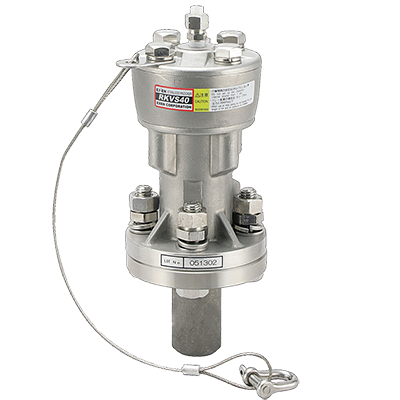
*When fixing the body with attached bolts, spring washers, and Hard Lock Nut, observe the tightening torque. If the tightening torque is low, the nut may be loosened by the impact at startup.
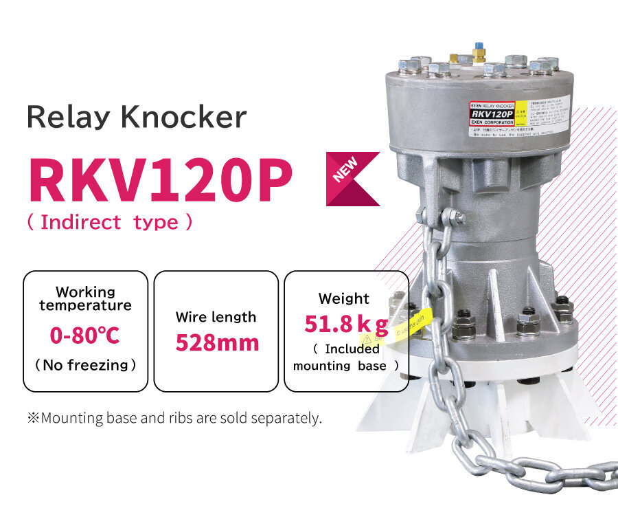
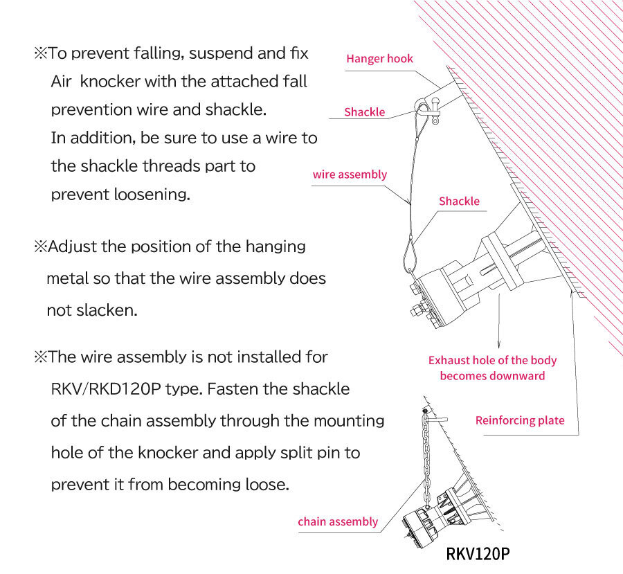
* To prevent the body from falling, suspend it with the attached fall prevention wire and fix them. As for the screw section of shackle, be sure to prevent the screw from being loosened with a wire.
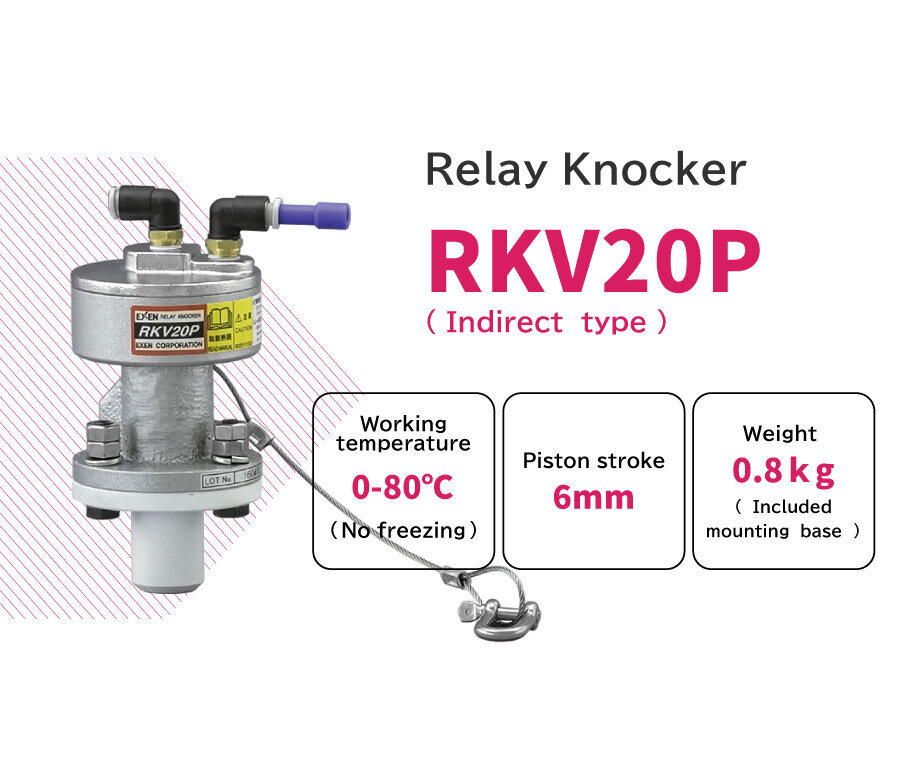
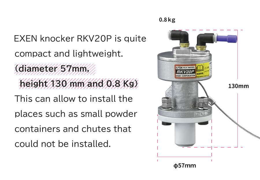
* Numerical values given in M6 are the bolting torque of the double nut. They are applied to RKV20P.
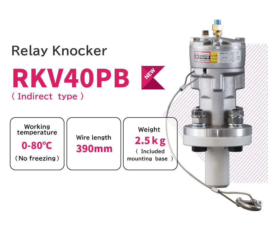
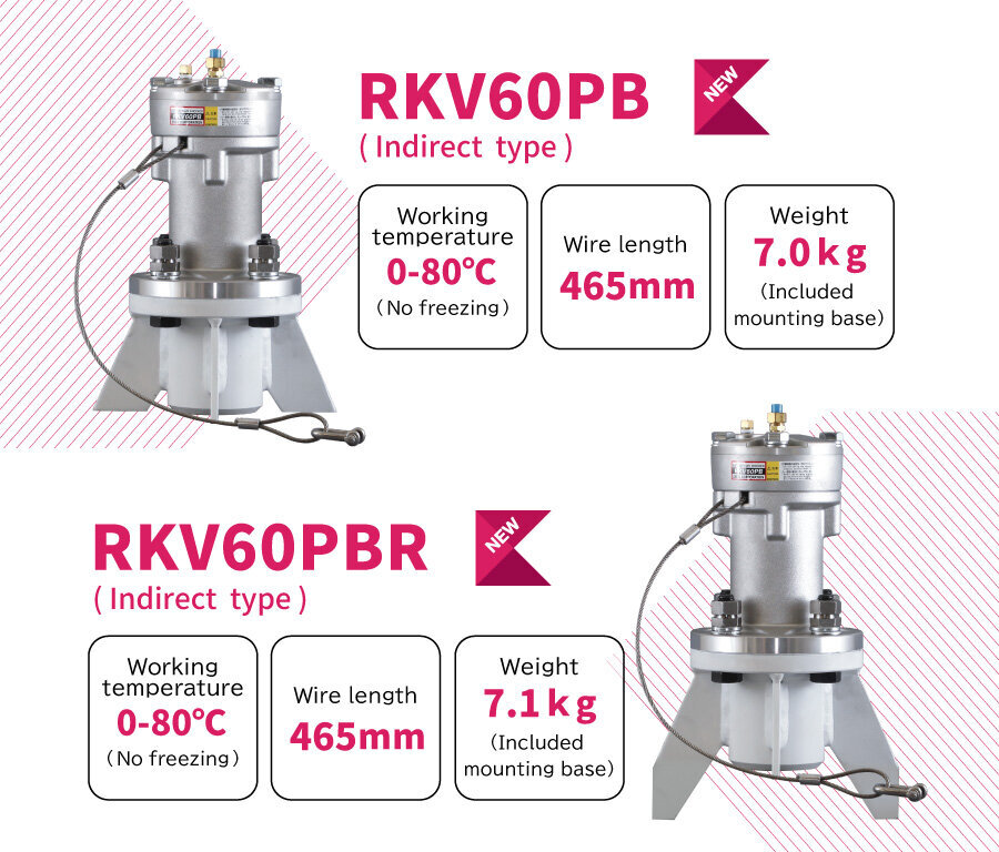
* Numerical values given in M8~M20 are the bolting torque of the hard rock nut. They are applied other than RKV20P.