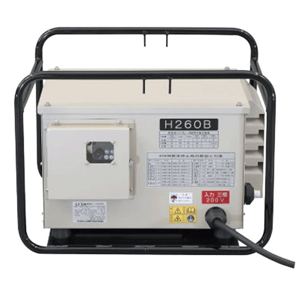
High-Frequency Vibrator Water-Resistant Inverter
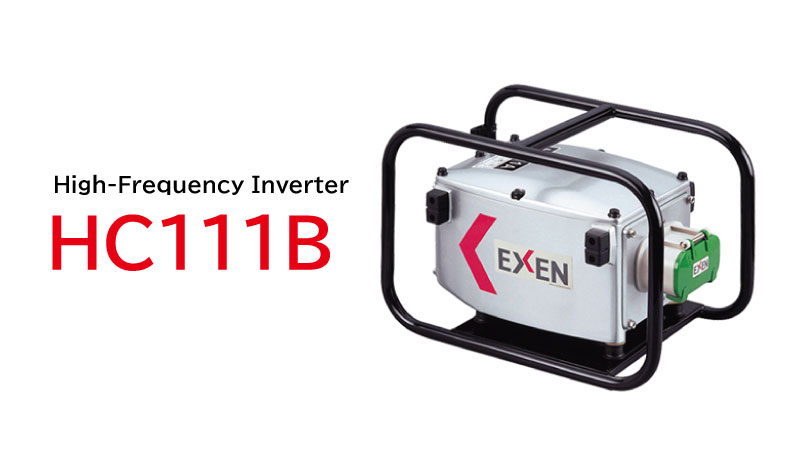
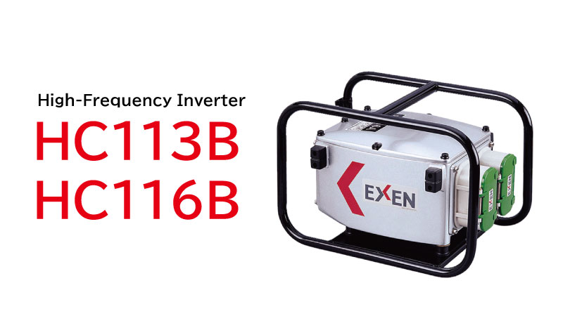
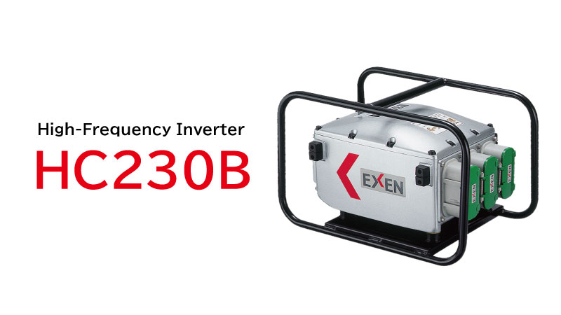
Product Overview
Water-Resistant Inverter is specifically designed for concrete vibrators, featuring a sealed structure that prevents water and dust from entering the inverter even under the harsh conditions of concrete placement. The inverter is equipped with an error indication function and multiple safety circuits, helping improve operational efficiency while ensuring safe operation.
Key Features
Excellent Water Resistance
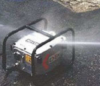
The aluminum die-cast housing provides excellent water resistance, achieving protection equivalent to IP55 and helping prevent water ingress. The enhanced water-resistant design allows the use of a high-pressure washer for easy cleaning of mortar and other debris after operation. The inverter is designed with separate compartments for the control board and serviceable components such as the output receptacle and operating switches, helping minimize the impact on the inverter’s core electronics in the event of component damage.
(When cleaning, do not place the unit on its side or upside down. Do not direct high-pressure water jets at the switch gasket or bottom cooling fan, as this may result in damage or malfunction.)
LED Error Indication
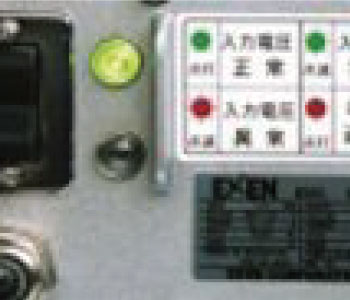
The single-phase inverter is equipped as standard with an LED warning function that alerts the operator when the input voltage falls outside the allowable operating range. The LED indicator also allows easy identification when the inverter stops output due to vibrator overload or a short circuit.
- Green LED (Steady) – Normal Input Voltage
- Green LED (Flashing) – Input Voltage Warning
- Red LED (Flashing) – Input Voltage Fault
- Red LED (Steady) – Output Stopped Due to Overload or Other Faults
Overvoltage Protection Circuit
The overvoltage protection circuit disconnects the power supply when the input voltage rises abnormally, helping protect the inverter from damage.
Ground Fault Protection Circuit
The ground fault protection circuit detects electrical leakage between the inverter and vibrator, automatically disconnecting the power supply to help ensure operator safety.
Overload and Short Circuit Protection
Built-in overload and short circuit protection automatically stops output when the vibrator is overloaded beyond the inverter’s rated capacity or when a short circuit occurs, helping protect the inverter from damage.
Constant Voltage Output Circuit
The constant voltage output circuit maintains a stable output voltage even when the input voltage fluctuates, helping prevent a reduction in vibrator performance. Provides stable and consistent vibration performance.
Easy Product Management
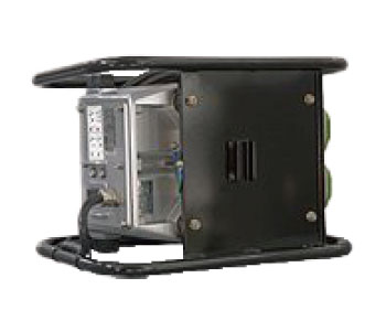
Up to three inverters can be stacked for storage, helping reduce storage space requirements. Locking brackets on the bottom of the unit allow up to three inverters to be securely stacked for storage.
Adjustable Frequency with Digital Display
The digital display allows quick and precise output frequency adjustment for easier operation.
Specifications
Water-Resistant Inverter
Metric
| Model | Input | Output | No. of Output Sockets | Weight (kg) | ||||||
|---|---|---|---|---|---|---|---|---|---|---|
| Capacity (kVA) | Voltage (V) | Current (A) | Frequency (Hz) | Capacity (kVA) | Voltage (V) | Current (A) | Frequency (Hz) | |||
| HC111B | 1.3 | 100-115 | 13-11 | 50 / 60 | 1.03 | 48 | 12.4 | 240 | 1 | 9.8 |
| HC113B | 1.5 | 15-13 | 1.3 | 15.0 | 2 | 10.0 | ||||
| HC116B | 2.0 | 20-17 | 1.6 | 19.0 | 10.1 | |||||
| HC230B | 3.8 | 200 | 11.0 | 3.0 | 36.0 | 100-240 | 3 | 15.5 | ||
Imperial
| Model | Input | Output | No. of Output Sockets | Weight (lb) | ||||||
|---|---|---|---|---|---|---|---|---|---|---|
| Capacity (kVA) | Voltage (V) | Current (A) | Frequency (Hz) | Capacity (kVA) | Voltage (V) | Current (A) | Frequency (Hz) | |||
| HC111B | 1.3 | 100-115 | 13-11 | 50 / 60 | 1.03 | 48 | 12.4 | 240 | 1 | 21.7 |
| HC113B | 1.5 | 15-13 | 1.3 | 15 | 2 | 22.1 | ||||
| HC116B | 2 | 20-17 | 1.6 | 19 | 22.3 | |||||
| HC230B | 3.8 | 200 | 11 | 3 | 36 | 100-240 | 3 | 34.2 | ||
* Weight includes the cable (0.95 kg / 2.1 lb for HC111B to 116B, 1.3 kg / 2.9 lb for HC230B).
* Please refer to each page for "Extension Cable Selection Chart" and "High-Frequency Vibrator Available Units Table".
HC-B Indicator Status Guide
| Vibrator | LED Indicators | Switch | Input Voltage | Abnormal State | ||
|---|---|---|---|---|---|---|
 Green Green |  Red Red | Status | Voltage | |||
| Weak |  Blinking Blinking |  Off Off | ON | Warning | 60–80V | Occurs when input voltage drops due to extended power cables or other factors. |
| Off |  Blinking Blinking | Abnormal | – 60V | |||
| Stop | On | On | ON | Normal | 80–120V | Occurs when a short circuit is detected in the vibrator or when the inverter shuts down output due to overload caused by operating beyond the allowable number of connected vibrators. |
| Blinking | Warning | 60–80V | ||||
| 120–140V | ||||||
| Off | Abnormal | – 60V | ||||
| Stop | Off | Off | OFF | Abnormal | 140V – | Occurs when the input voltage exceeds the allowable operating range. |
| Normal Warning | 60–140V | Occurs when a ground fault is detected in the inverter or vibrator. | ||||