Welding Guide for Knocker Reinforcing Ribs and Reinforcing Plates
Reinforcement Rib Installation and Safety Measures for RKV Series Knockers
To ensure secure installation and safe operation of RKV Series Knockers, this section describes the proper welding procedures for reinforcing ribs (mounting bases) and the necessary safety precautions during installation.
Proper Installation of Reinforcement Ribs
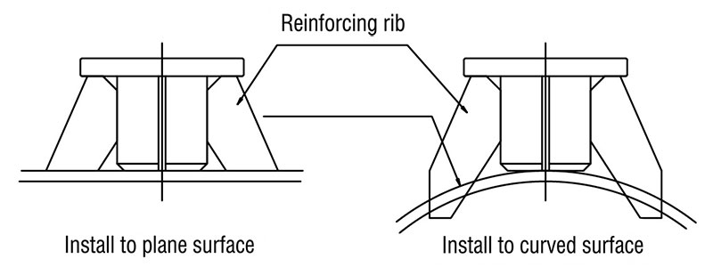
To ensure efficient transmission of the knocker's impact force to the equipment and to prevent damage to the storage vessel, it is important that the reinforcing ribs be welded in the proper locations and orientations. Refer to the illustration below and ensure that the reinforcing ribs are positioned correctly and that welding is performed within the specified weld areas.
Thorough Fall Prevention Measures
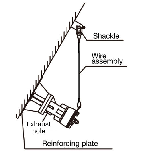
The intense vibration generated by the knocker may cause the unit itself to fall if bolts loosen or the mounting base is damaged. As a safety precaution, always provide a fall-prevention device, such as a safety wire, as shown in the figure below.
Reinforcement Plate Installation and Welding Specifications
If the mounting surface is thin, a reinforcement plate should be welded in place. Proper installation of the reinforcement plate is extremely important for efficiently transmitting impact force and preventing damage to the hopper or storage vessel.
Fundamentals of Welding and Structural Strength
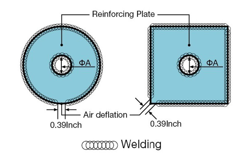
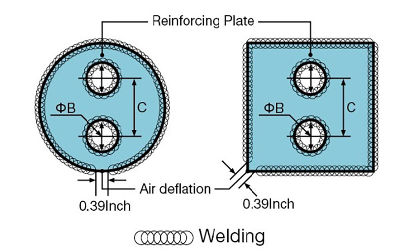
When welding a reinforcement plate to a hopper, perform a continuous weld around the entire perimeter to eliminate gaps. However, to prevent air-cushioning effects and ensure efficient transmission of impact force, leave one unwelded section as an air vent. Significant impact loads are applied to the welded areas during knocker operation. To prevent possible failure or detachment, always apply sufficient weld reinforcement and maximize weld build-up wherever possible.
Recommended Welding Electrodes
- For carbon steel: Use JIS Z3211 E4319 equivalent electrodes or higher (e.g., Kobe Steel B-10).
- For stainless steel (SUS): Use JIS Z3221 ES308-16 equivalent electrodes or higher (e.g., Kobe Steel NC-39).
Reinforcement Plate Dimensions (Unit: mm)
| Model | Square Plate | Round Plate | Reinforcement Plate Hole Diameter | Pitch | |
|---|---|---|---|---|---|
| ΦA | ΦB | C | |||
| RKV/RKD/(RKVS) 30PB | □150×t3.2 (3.0) | Φ150×t3.2 (3.0) | 15 | 20 | 52 |
| RKV/RKD/(RKVS) 40PB | □200×t3.2 (3.0) | Φ200×t3.2 (3.0) | 80 | ||
| RKV/RKD/(RKVS) 60PB | □300×t4.5 (4.0) | Φ300×t4.5 (4.0) | 55 | 90 | |
| RKV/RKD 80PA | □400×t4.5 | Φ400×t4.5 | 25 | 120 | |
| RKV/RKD 100PA | □500×t6.0 | Φ500×t6.0 | 85 | 140 | |
| RKV/RKD 120P | □600×t9.0 | Φ600×t9.0 | 95 | 30 | 160 |
* Values in Parentheses Apply to Stainless Steel (SUS) Models
RKV (Vibration Type) Reinforcement Plate Welding Diagram
RKD (Direct Impact Type) Reinforcement Plate Welding Diagram
Installation of Base Assemblies and Reinforcement Ribs
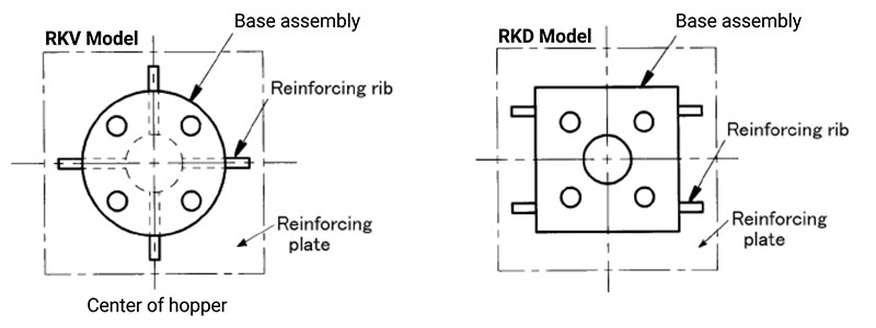
Welding Instructions and Precautions
- Weld the base assembly continuously around its entire perimeter, ensuring that the bolt holes remain symmetrical.
- Cut the base reinforcement ribs to match the shape of the installation surface, then weld them continuously around their entire perimeter while maintaining symmetry.
Recommended Reinforcement Rib Installation by Model
- RKD60PB and larger models: Cut the supplied base reinforcement ribs to match the mounting surface and weld them in place.
- RKV/RKD 30PB and 40PB: Reinforcement ribs are generally not required; however, installation is recommended when additional durability is desired.
- RKVS60 and RKV61PB and larger models: Reinforcement ribs are factory-welded to the base. Cut the ribs to fit the installation surface and weld them accordingly.