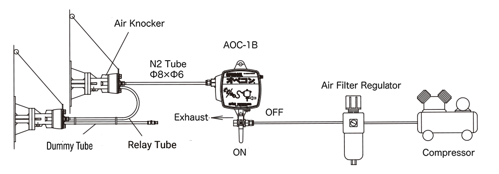
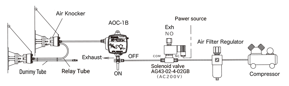
Air Knocker Piping Connection Guide
Piping Configuration Selection and Important Notes
Select either the standard piping configuration or the relay piping configuration, referring to the piping examples provided.
- When using only one circuit with a dedicated control panel (HKE or HKA Series), seal the unused circuit port with a plug.
- The dedicated control panels (HKE and HKA Series) can accommodate knockers on both Circuit A and Circuit B. However, the charging and impact operations of the two circuits are performed in opposite phases.
1.Standard Piping Examples
A. Using AG44 Three-Way Solenoid Valve
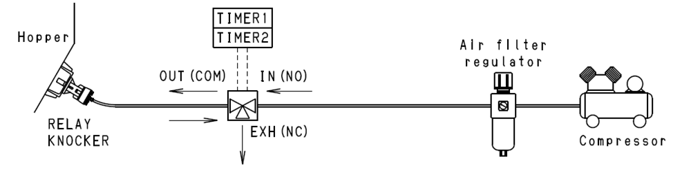
B. Using HKE/HKA Dedicated Controller
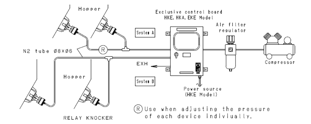
(Circuit A and Circuit B operate alternately.)
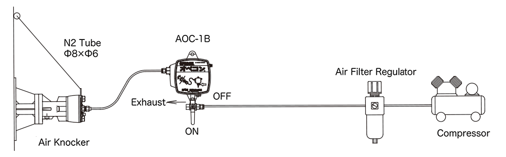
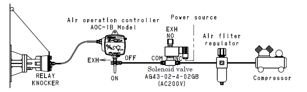
C. Using AOC-1B Air-Operated Controller
Automatic control can be achieved by installing an AG43-02-4-02GB solenoid valve upstream of the AOC-1B.
D. Using AG44 Three-Way Solenoid Valve and MV-1 Master Valve
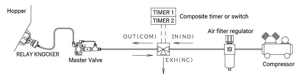
Using the MV-1 Master Valve
- When the extension tube between the controller or solenoid valve and the knocker is long, use an MV-1 Master Valve to prevent operational problems and reduced impact force.
- When using the Master Valve, maintain a supply pressure of 0.4 MPa or higher. Keep the distance between the knocker and the Master Valve within 1 m, and the distance between the Master Valve and the controller or solenoid valve within 51 m.
2.Relay Piping Examples
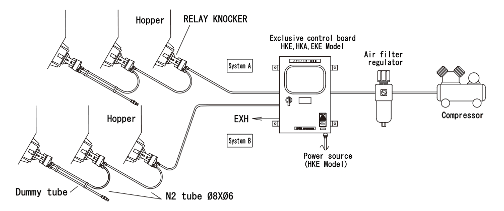
- Relay piping is a piping method in which multiple knockers are connected in a series.
In this arrangement, a relay tube is connected from the air tank of the knocker nearest the three-way valve to the supply/exhaust port of the next knocker in the sequence. - The maximum number of connected knockers depends on the control method (control device used). Refer to piping examples E, F, and G below.
E. Using AG44 Three-Way Solenoid Valve (Up to 6 Knockers)
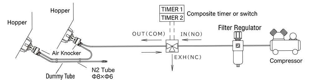
F. Using HKE/HKA Dedicated Controller (Up to 11 Knockers per Circuit)
G. Using AOC-1B Air-Operated Controller (Up to 4 Knockers)
Automatic control can be achieved by installing an AG43-02-4-02GB solenoid valve upstream of the AOC-1B.