Mini blaster

  • Mini blaster
  • Mini blaster
  • Mini blaster
  • Mini blaster

Mini blaster

Multi-nozzle blaster with easy on-site installation and variable injection direction

This product is used for the following applications:

  • 01Installation in combustion facilities in environmental recycling plant
  • 02Prevention of blockage in the positive and negative electrode storage hopper in the secondary battery material manufacturing plant
  • 03Prevention of adhesion of ceramic material in the hopper
  • 04Ejection enhancement of resin pellet
  • 05Ejection enhancement of powdered paint

Used in the following places:

Features

The pneumatic Mini Blaster instantly blasts the compressed air injected in the tank through solenoid valve. Using compressed air is safe and operational cost is low. Because tank is separated from driving section, maintenance is easy and durability is fully considered. This small and lightweight product is used mainly for small capacity hopper and chute.


Multi-nozzle included as standard equipment

The blasting type can be selected from the vertical nozzle that blasts in one direction and the radial nozzle that blasts in all directions (360 degrees). Vertical nozzle is convenient because it can be installed in multiple ways depending on the blockage situation. The nozzle construction cost is low because the nozzle, a standard accessory, can be used, and the blasting force can be adjusted by selecting the blast type and adjusting the operating pressure. Therefore, mischoice of model or wrong installation work is rare.

Mini blaster

Effect of multi-nozzle

It is possible to change the blast direction of multi nozzle by replacing its front and back sides of multi-nozzle plate. If, for example, the pneumatic Mini Blaster does not bring the effect, the multi-nozzle setting can be changed on site, which reduces the number of changes of installation.

Mini blaster

Easy on-site installation

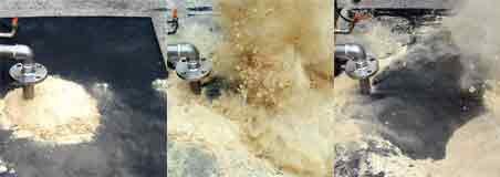
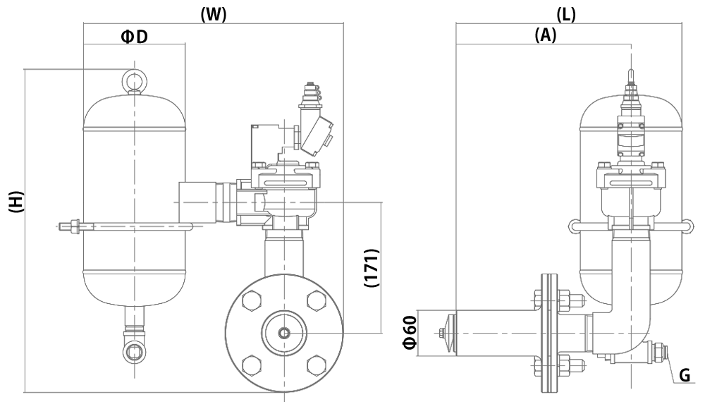
Drill a hole with the same size as that of diameter of nozzle pipe on hopper or tank wall, insert the nozzle, and then do welding. This completes the installation. Easy installation and easy completion of installation reduce the installation cost. Previously, the nozzle was directly welded to the hopper, but in this model, the previous specification is changed to that in which the nozzle is pulled out and inserted with the base mounted to the target object. In addition, the nozzle tip is equipped with heat-resistant silicon O-ring to prevent the powder from leaking.

Mini blaster

Improvement of operational environment

The use of knocker or vibrator for eliminating blockage will reduce the noise on site, allowing for the night operation. Improvement of working environment and no metallic fatigue owing to striking and vibration will increase the product efficiency. We have received a comment from a plant worker that he can hold a consultation with smaller voice that before.


Simple structure and high durability

All tank models adopts the stainless steel SUS304 that is resistant to rust, and has a simple structure with high durability and easy maintenance. This reduces the number of inspections and maintenance, resulting in cost reduction.

Mini blaster

Operating principle of mini blaster

1. The diaphragm blocks the injection port with the power of solenoid valve OFF to cause the compressed air to be supplied into the tank.
2. The supplied compressed air starts to be charged into the tank, piping, and solenoid valve. When the supplied pressure is equal to that in the tank, piping, and solenoid valve, the charge is completed.
3. When the power of solenoid valve is turned ON, the diaphragm moves away from the injection port to cause the compressed air in the tank to be instantly injected from the injection port.

Mini blaster

List of models

Model Code Number Product Drawing Download
EMB1.5-3A(100V) 000826000 (*1) Product Drawing
Download
EMB1.5-3A(200V) 000829000 (*1) Product Drawing
Download
EMB1.5-6A(100V) 000827000 (*1) Product Drawing
Download
EMB1.5-6A(200V) 000830000 (*1) Product Drawing
Download
EMB1.5-10A(100V) 000828000 (*1) Product Drawing
Download
EMB1.5-10A(200V) 000831000 (*1) Product Drawing
Download

*1 Because this product is a built-to-order product, contact EXEN for information on price and delivery time.

Specification

EMB-A

Model Outlet dia.
(in)
Valve
port
Valve
voltage
Working
presure
(MPa)
Available
gas
Tank
capacity
(L)
Material Weight
(kg)
Valve Tank
EMB1.5-3A 1.5 Type
Poppet
Structure
Solenoid
Valve
100V/200V
Single Phase
0.1-0.7 Compressed
Air
3 ADC12 SUS304 10.2
EMB1.5-6A 6 12.4
EMB1.5-10A 10 17.8

(Imperial System)

Model Outlet dia.
(in)
Valve
port
Valve
voltage
Working
presure
(PSI)
Available
gas
Tank
capacity
(Cu. Ft)
Material Weight
(lb)
Valve Tank
EMB1.5-3A 1.5 Poppet
Structure
Solenoid
Valve
100V/200V
Single Phase
15-102 Compressed
Air
0.11 ADC12 SUS304 22.5
EMB1.5-6A 0.21 27.3
EMB1.5-10A 0.35 39.2

*Because the magnetic valve is not included as standard equipment, specify the voltage.

Electric specification of magnetic valve

Rated voltage AC100V/AC200V
Apparent power Retention:7.5/5.5VA(50/60Hz)
Startup: 20/17VA(50/60Hz)
Power consumption 4.0/3.4W(50/60Hz)
Insulation class Class B
Connection T type terminal box(G1/2)
Connection terminal R1.25-3
Cable VCT0.75mm 2

*For manufacturing of special product with explosion-proof specification, contact our branch office.

Dimensions, installation, control panel

Product dimensional drawings

Product dimensional table

Model A φD H W L Inlet port
G
EMB1.5-3A 229 133 423 340 295 φ10
15A(1/2B)
EMB1.5-6A 643
EMB1.5-10A 219 583 425 338

(Imperial System)

Model A φD H W L Inlet port
G
EMB1.5-3A 9.0 5.2 16.7 13.4 11.6 φ10
15A(1/2B)
EMB1.5-6A 25.3
EMB1.5-10A 8.6 23.0 16.7 13.3

Installation method

■Calculation of necessary amount of air

V: Necessary amount of air (L/min (ANR)),  Vo: Total tank capacity (L)
P: Operating pressure (MPa),  M: Operating cycle (min)
Example) When using six EMB1.5-6A models at an operating pressure of 0.7MPa, at an interval of 5 minutes:

Sufficiently usable with a compressor of 0.75kW.