Powder Flow in Storage Vessels and Blockage Mechanisms
Flow Patterns in Storage Tanks and Related Challenges
As shown in the figure below, the flow patterns of powders inside storage vessels (such as silos and hoppers) can be broadly classified into two types: mass flow and funnel flow.
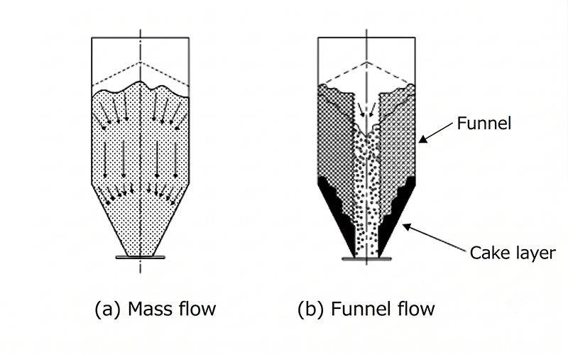
Figure 1. Typical flow patterns in a storage vessel.
If all storage vessels operated under mass flow conditions, in which the entire powder inside the vessel moves uniformly, flow-aid equipment and discharge-assistance devices would not be required.
In practice, however, many vessels exhibit funnel flow, where only the central flow channel moves freely while material near the walls remains stagnant. As a result, various flow-aid devices and discharge-assistance systems are commonly installed to promote stable and continuous discharge.
Mechanism of Arching (Blockage)
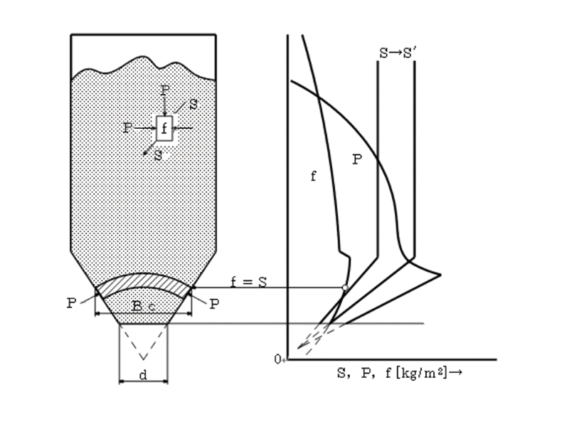
Figure 2. Compressive arch and arch diameter in a hopper.
How Arching (Blockage) Occurs in a Hopper Figure 2 illustrates the mechanism by which arching, a common cause of blockage in storage hoppers, occurs.
- f (Bulk Material Strength):
The strength of the bulk material after being compacted by the pressure within the stored powder bed. - S(Shear Force Acting on the Bulk Material):
The downward force generated by the weight of the material, acting to break the arch. This force is influenced by factors such as wall friction and hopper angle.
The relationship between these forces determines whether material flow continues or blockage occurs:
| Condition | Result |
|---|---|
| f < S | The material remains free-flowing and continues to discharge. |
| f > S | The material consolidates and arching (blockage) occurs. |
The point at which f = S is known as the Critical Outlet Diameter. In theory, arching can be prevented by designing the hopper outlet larger than this critical diameter.
In practice, however, installation space limitations and downstream equipment requirements often restrict outlet design, making blockage prevention more challenging.
Locations Where Blockage Is Most Likely to Occur
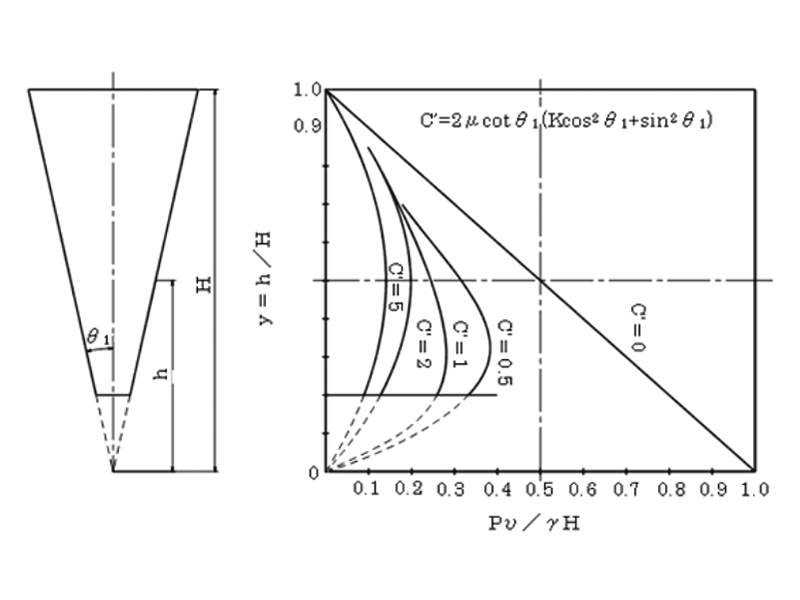
Figure 3. Powder pressure distribution in a conical hopper.
To proactively prevent blockages, it is essential to identify the locations within the storage vessel where flow problems are most likely to occur.
As shown in Figure 3, blockages are most likely to occur in the vicinity of the maximum (peak) powder pressure.
Specifically, the maximum powder pressure occurs when the ratio y=h/Hy = h/Hy=h/H is approximately 0.3 to 0.4, where hhh is the height above the vessel outlet and HHH is the total height of the bulk material inside the storage vessel.
In the region where the powder pressure reaches its peak, the bulk material is subjected to the highest degree of compression (consolidation), resulting in a rapid increase in powder strength (fff). Consequently, stable arches that impede material flow and discharge are more likely to develop.
Therefore, preventing excessive compression of the bulk material in this critical region and maintaining good flowability are essential design considerations for achieving stable and reliable discharge.