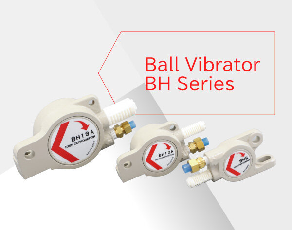
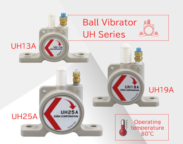
Ball vibrator is a compact vibrator that generates powerful centrifugal force vibration via high-speed rotation of steel ball by compressed air. This vibrator has simple principle and structure and can be used easily. It is generally used for preventing clogging in hopper chute, but the applications are expanded depending on ideas. Frequency and centrifugal force can be freely changed only by operation of air pressure. Depending on the on-site installation conditions, selection can be made from model lineup of BH-A, CH-A, and UH-A, which are different in positions of air supply and exhaust. (Supplying lubricant with an oiler is required)
Frequency and centrifugal force can be easily changed.
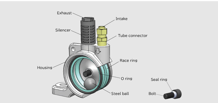
A steel ball that rotates at high speed inside the housing with compressed air generates strong centrifugal vibration.
Simply operating the pressure of compressed air allows frequency and centrifugal force to be easily changed.
※ Use a lubricator (Oiler) to maintain its performance.
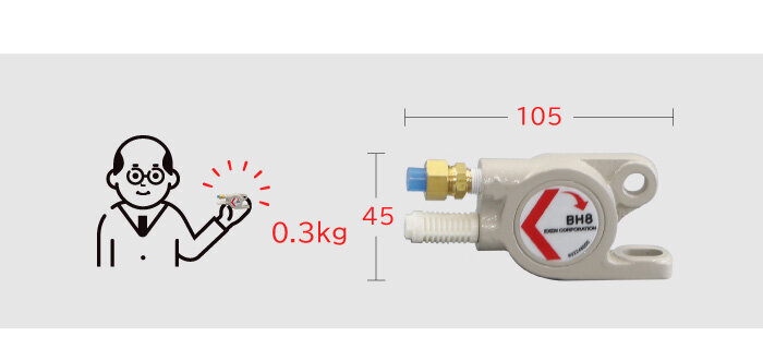
Lightweight and small
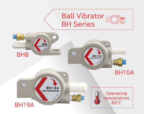
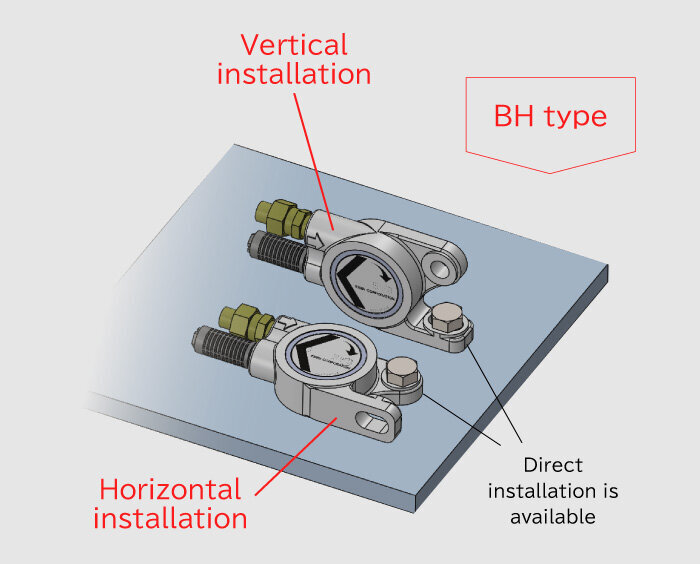
The smallest BH8 with the mounting width of 18 mm and the weight of 0.3 kg enables installation in narrow spaces where it is difficult to install a conventional vibrator. (BH8 type can be installed in two directions.)
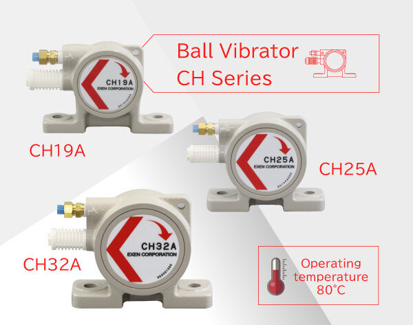
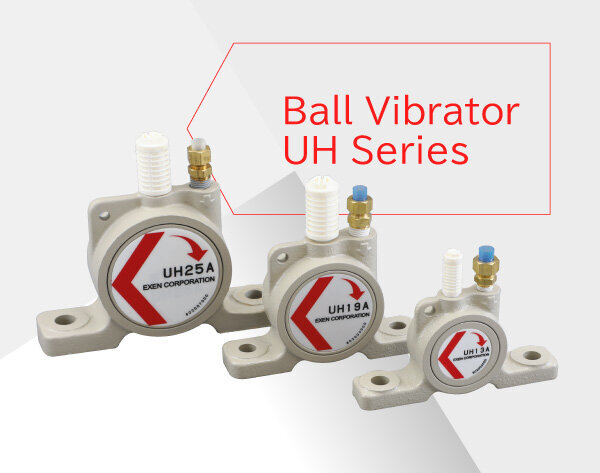
Depending on the on-site installation conditions, selection can be made from model lineup of BH-A, CH-A, and UH-A, which are different in positions of air supply and exhaust. This series can be also used in water because of its high airtightness. (Assuming that exhaust pipe is extended to the atmosphere)
Depending on the on-site installation conditions, selection can be made from model lineup.
Since the intake direction differs depending on the model, it is possible to select the model according to the piping restrictions of the air tube. BH type that can be installed with a single bolt is also available.
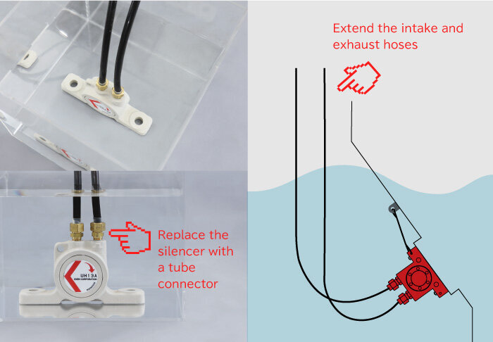
Completely airtight waterproof structure
The waterproof structure of this series enables use in watery environments. By attaching a tube connector to the exhaust port (replace the silencer with a tube connector) and extending the intake and exhaust hoses, this vibrator can be attached to an underwater object. (Note: If the exhaust tube is extended, the vibration efficiency will decrease.)
Easy maintenance
Ball can be replaced in all models. Replacement maintenance can be easily conducted by loosening bolts on the side cover, removing the side cover, and the replacing the ball. (Note: If the internal raceway ring is significantly worn, only replacing the ball will not repair the product)
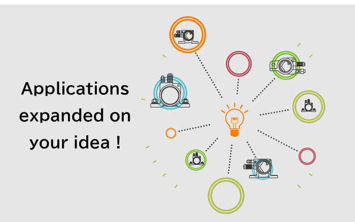
Applications expanded on your idea
Although the ball vibrator is generally used to prevent minor clogging of powder in hopper or chute, it can be utilized as a motor for vibration table used for filling. Applications are expanded on various ideas, such as applying the vibration to eliminate buildup in parts supply line of production lines.
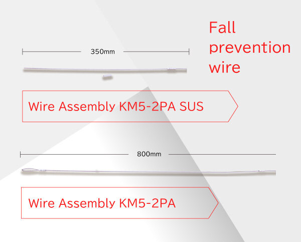
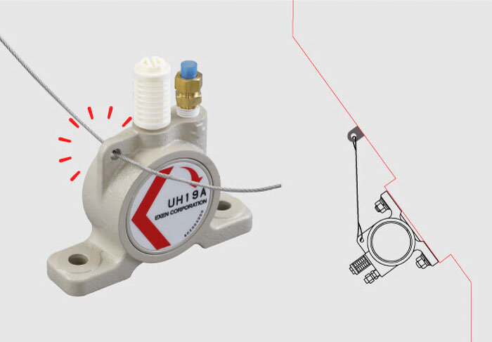
Mounting holes for safety wire are provided as standard
All models of ball vibrator are provided with mounting holes for the fall prevention wire.
It is highly recommended to mount the wire to ensure the safety in plant. (Wire is optional)
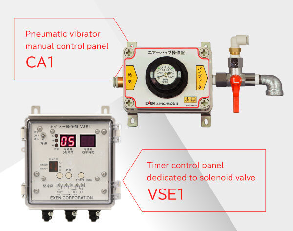
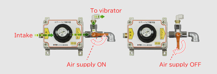
Pneumatic vibrator manual control panel
CA1 type is a control panel for the manual pneumatic vibrator, which provides easy operation for the pneumatic vibrator and ball vibrator, and piston vibrator. Preparing only air tube and pressure air allows quick operation.
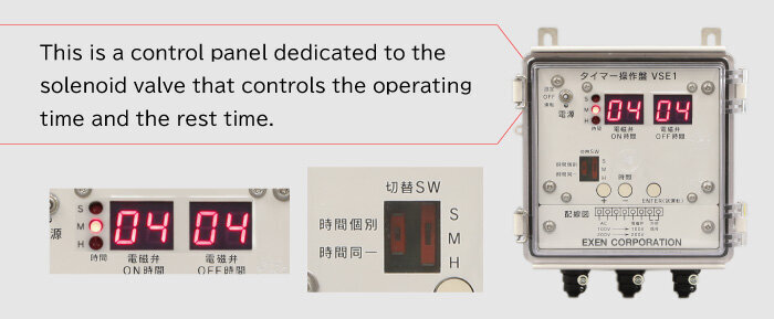
Timer control panel dedicated to solenoid valve
Timer control panel VSE1 corresponds to input power supply AC100V / AC200V. This is a control panel dedicated to the solenoid valve that controls the operating time and the rest time.