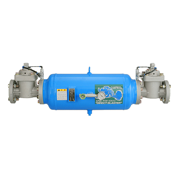
Air Blaster Direct Blaster
Product Overview
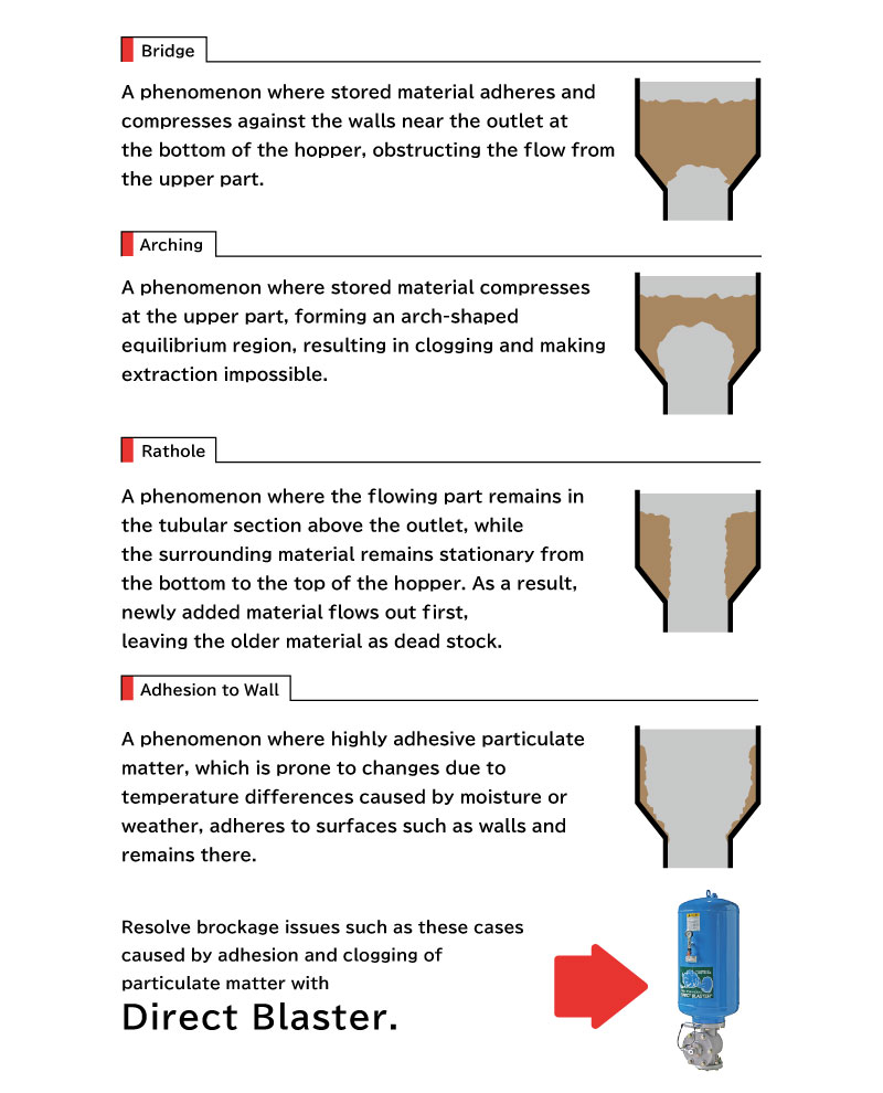
The Blaster is designed to unblock accumulated powders and granular materials inside large tanks and silos by instantly discharging stored compressed air with explosive force.
Manually clearing blockages inside tanks and silos can be hazardous and may result in serious workplace accidents.
With simple one-touch operation, the Direct Blaster clears blockages safely and efficiently, providing a reliable solution to material flow problems while reducing operator risk.
Key Features
Clearing Blockages in Powder and Granule Storage Tanks
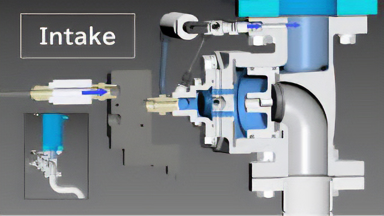
Direct Blaster Operating Principle
- When compressed air is supplied via a three-way valve, the umbrella-shaped valve is pushed toward the exhaust port side.
- The compressed air passing through the valve pushes the piston toward the discharge port.
- When the piston is pushed to its limit and blocks the discharge port, compressed air is directed through the tube and charged into the tank.
- Charging is complete when the tank pressure reaches the same level as the supply pressure.
- The valve and piston are drawn in the opposite direction, allowing the compressed air stored in the tank to be released instantaneously through the discharge port.
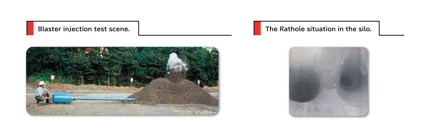
Effective Material Flow Promotion
By injecting compressed air directly into the material, the system delivers superior blockage removal performance and improved material flow, while helping reduce dead stock in silos.
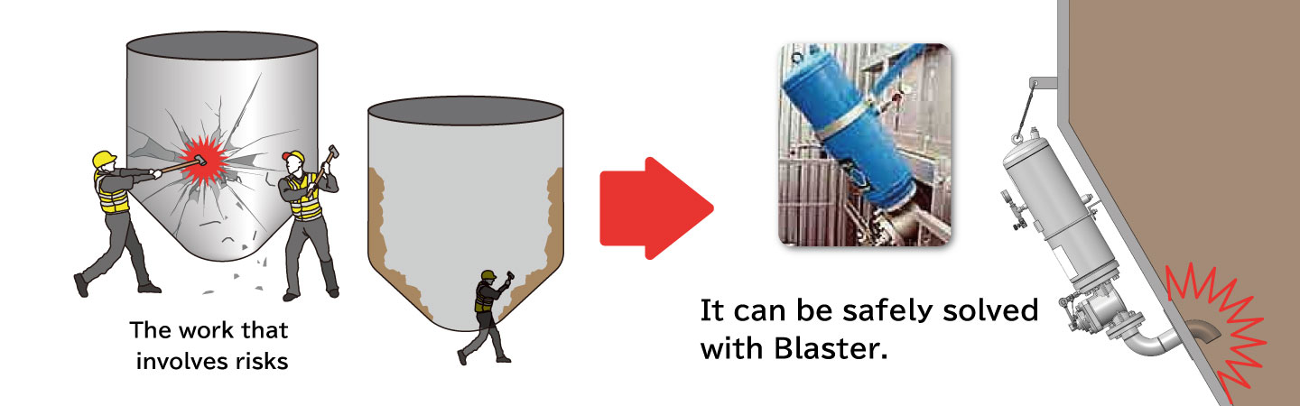
Safety First
Clearing blockages from tanks and silos has traditionally been a labor-intensive task that can expose workers to significant safety risks.
This Twin Blaster provides a safer alternative by eliminating the need for hazardous manual clearing operations.
Adjustable Blasting Force Through Pressure Control
The umbrella-type valve design allows precise control of spray force simply by adjusting the air pressure supply.
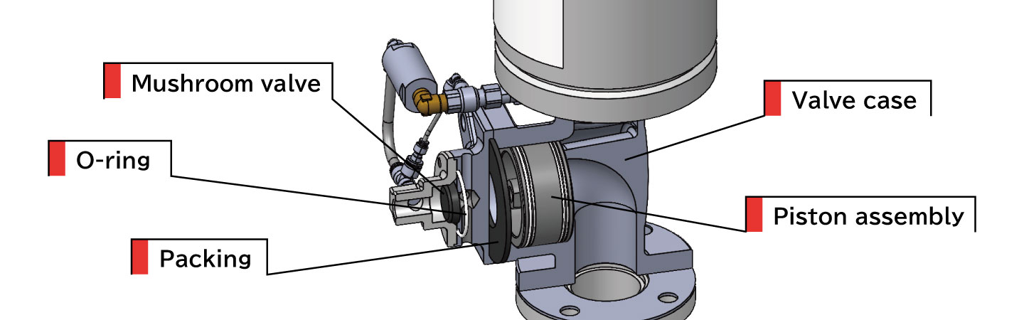
Improved Maintainability
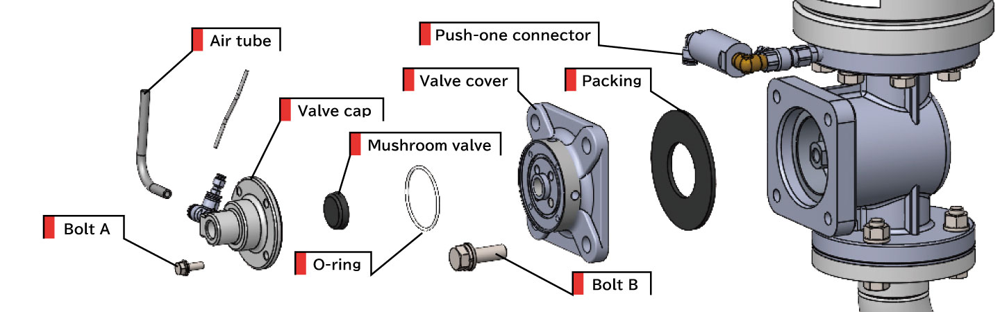
Maintenance has been greatly simplified since worn components inside the valve can now be replaced directly at the installation site, thereby reducing downtime and maintenance costs.
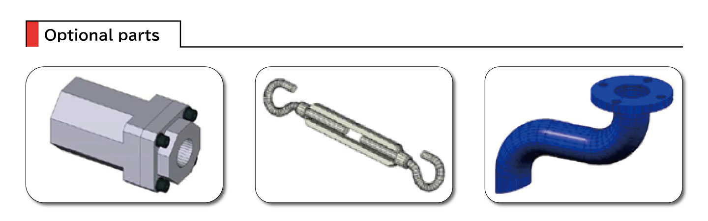
Optional Accessories
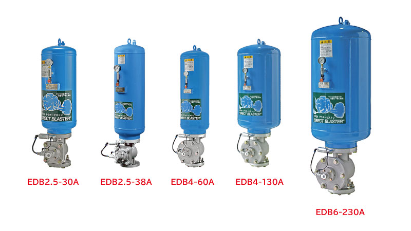
Extensive Lineup for Various Operating Conditions
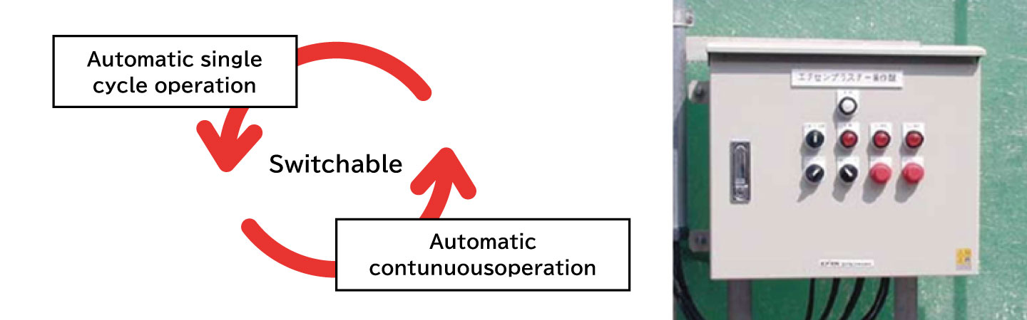
On the automatic control type, a selector switch allows the operator to choose among Manual, Automatic Single-Cycle and Automatic Recycle modes, enabling flexible operation according to the severity and nature of the blockage.
Models
| Model | Item Code | Downloads |
|---|---|---|
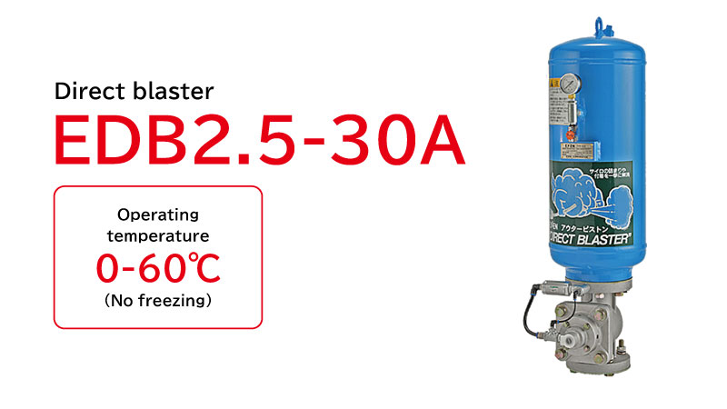
| EDB2.5-30A | 000525100 | Downloads |
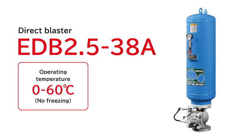
| EDB2.5-38A | 001264100 | Downloads |
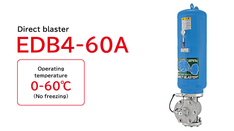
| EDB4-60A | 000526100 | Downloads |
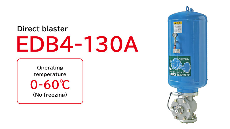
| EDB4-130A | 000527100 | Downloads |
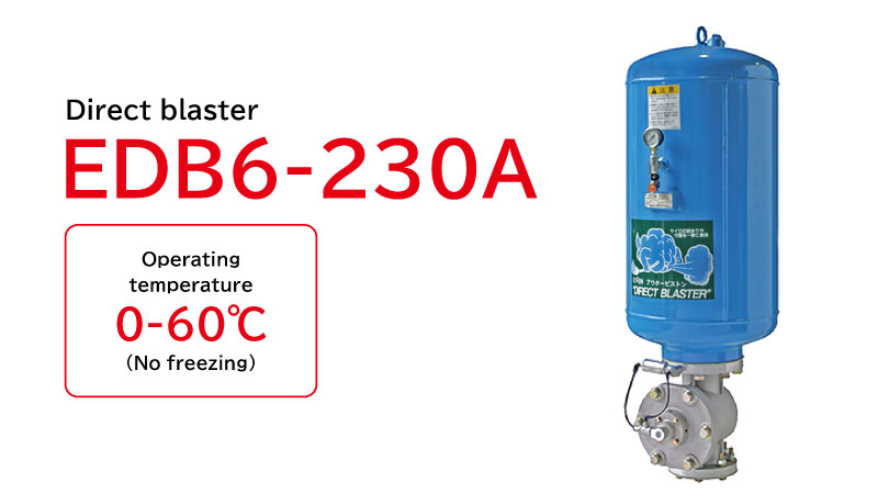
| EDB6-230A | 000528100 | Downloads |
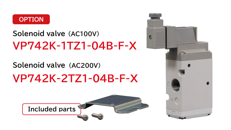
| Solenoid valve VP742K-1TZ1-04B-F-X(100V) | 500410000 | ― |
| Solenoid valve VP742K-2TZ1-04B-F-X(200V) | 500411000 | ― |
* Solenoid valve available as an option.
Downloads include instruction manuals and drawings. Contents may vary depending on the model.
Specifications
Direct Blaster
Metric
| Model | Outlet Dia. (in) |
Tank Capacity (L) |
Tank Maximum Allowable Operating Pressure (MPa) |
Operating Pressure (MPa) |
Available Gas | Coating | Weight (kg) |
|
|---|---|---|---|---|---|---|---|---|
| Inner Surface | Outer Surface | |||||||
| EDB2.5-20A | 2.5 | 20 | 0.97 | 0.3-0.7 | Compressed Air or Nitrogen Gas |
Epoxy Resin Coating | 38 | |
| EDB2.5-30A | 30 | 42 | ||||||
| EDB2.5-38A | 38 | 50 | ||||||
| EDB4-60A | 4 | 60 | 81 | |||||
| EDB4-80A | 80 | 81 | ||||||
| EDB4-130A | 130 | 103 | ||||||
| EDB6-230A | 6 | 230 | 168 | |||||
Imperial
| Model | Outlet Dia. (in) |
Tank Capacity (gal) |
Tank Maximum Allowable Operating Pressure (PSI) |
Operating Pressure (PSI) |
Available Gas | Coating | Weight (lb) |
|
|---|---|---|---|---|---|---|---|---|
| Inner Surface | Outer Surface | |||||||
| EDB2.5-20A | 2.5 | 5.28 | 141 | 44-102 | Compressed Air or Nitrogen Gas |
Epoxy Resin Coating | 83.78 | |
| EDB2.5-30A | 7.93 | 92.59 | ||||||
| EDB2.5-38A | 10.04 | 110.23 | ||||||
| EDB4-60A | 4 | 15.85 | 178.57 | |||||
| EDB4-80A | 21.13 | 178.57 | ||||||
| EDB4-130A | 34.34 | 227.08 | ||||||
| EDB6-230A | 6 | 60.76 | 370.38 | |||||
* The solenoid valve assembly is sold separately. Please check the required voltage before ordering.
* The tank is designed and manufactured with a maximum operating pressure of 0.97 MPa (140.7 psi).
Installation
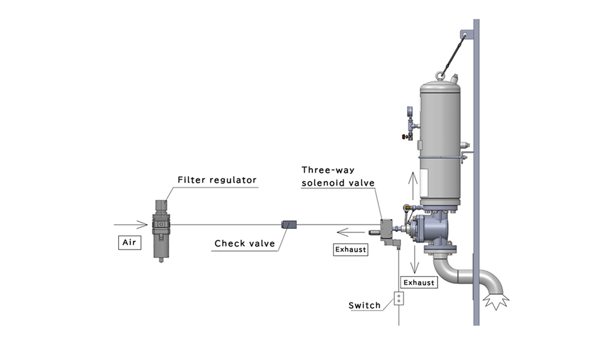
By using a control panel, multiple Direct Blaster units can be operated remotely
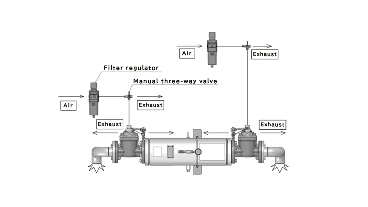
A single Direct Blaster unit can be operated either manually or electrically.
When handling powders or granular materials with a risk of dust explosion, the three-way solenoid valve can be replaced with an explosion-proof type to provide safe operation.
- When installing multiple blasters connected to the same air supply source, or when using aeration in conjunction with the system, be sure to install a check valve individually upstream of each solenoid valve on the air supply side. This prevents accidental blasting caused by pressure fluctuations or pressure reductions in the primary air supply line.
Electric
Manual
Calculation of Required Air Consumption
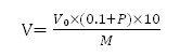
V :Required Air Volume(L/min(ANR))
Vo:Total Blaster Tank Capacity(L)
P :Operating Pressure(MPa)
M :Operating Cycle(min)
Example: Six EDB2.5-30A units operating at an operating pressure of 0.7 MPa with a 5-minute blasting interval.

A 2.2-kW compressor is sufficient for this application.
- Please use a compressor with an air delivery rate of 200 L/min (ANR) (1.5 kW) or higher.
If using an air compressor with an air delivery capacity of less than 200 L/min (ANR), install a receiver tank with a capacity of at least 10 L immediately upstream of the three-way solenoid valve.